General Pictures of Railroad
While some of the original rail was Atlas Flex
track laid in the early 1970s most mainline rail is
140 lb nickel silver laid on individual wooden ties, and in turn on
1/4" of cork. A 4000' roll of
16 guage magnet wire was obtained to run with each rail under the
table, connecting via every
rail joiner to insure electrical continuity. The layout is 65'
long and 15' wide on the north end
and 12 feet wide on the south end
With DC power wheel burning occurs unless separate pickups are
used. These pickups are
essentially sleds with 4 points of contact installed under the trucks
of tenders for steam
locomotives and on one of the diesel trucks. These sleds act as
rail cleaners as well as
pickups and have replaceable brass shoes mounted on printed circuit
board frames. The
spring holding the sled against the track is a 1" wide sheet of
phosphor bronze which
maintains solid horizontal position.
Mainline curve radii are a minimum of 6' with some old sidings as low
as 4'. The original
point to point layout had 4' turnarounds which were abandoned as
mainline when a major
extension of dual tracking on the west side was added. The east
side still had a section over
the trestle which was single track until the Overland truss bridge was
added which also included
a whole new set of rails from the north end for about 40 feet through 2
separate mountains
and using the mine siding as mainline with new rail and an improved
roadbed added. Dual
tracking of 6 more feet to the south of the mine siding was added so
dual track existed all the
way around.
All switches are custom made for each geometry with mainline switches
being # 8s or larger
and siding switches # 6s. Some switches overlap other switches to
minimize the space required.
Capacitor discharge powering of switch machines is used with added
voltage for those over 35
feet away. While digital individual engine controls was
used for several years it was abandoned
in favor of blocked straight DC powering due to the large number of
locomotives and the effort
necessary to adapt each new one. Also any momentary short messed
up the other locomotives
although the sloppy switch work (and track work) causing the shorts was
eventually eliminated.
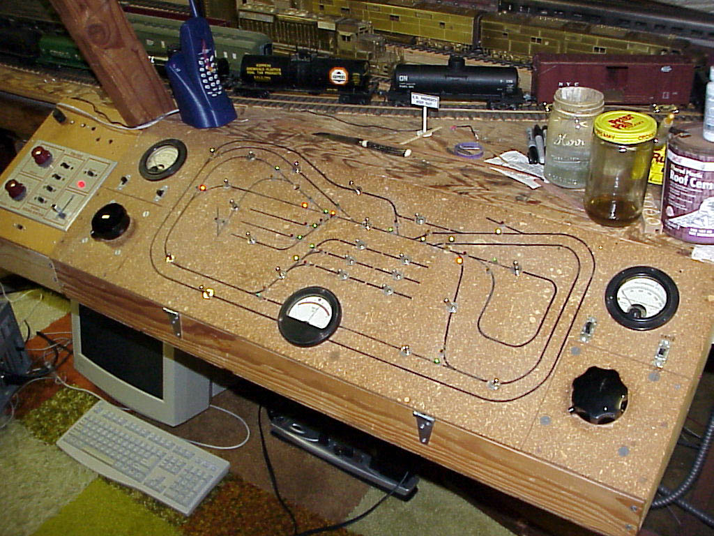
The basic power transformer for train power is a relatively large one
housed in a square foot
box with 20v, 40v and 60v taps. 6 amp variacs are used in front
of the AC to DC diode bridges
for train control.
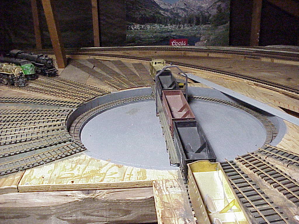
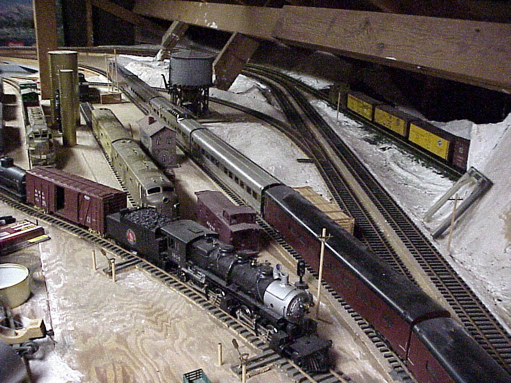
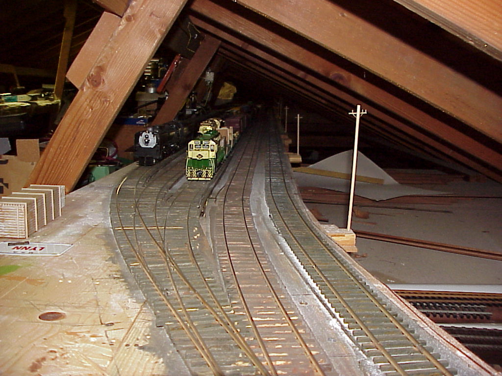
The following 2 pictures are at the northeast location of the layout
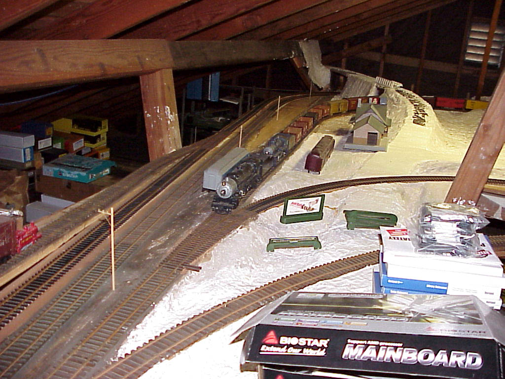
and the next 2 are at the
northwest part. The left picture of row 3 is 3 long sidings on
the west part of the layout
capable of holding 25 car trains.
Click on pics to enlarge
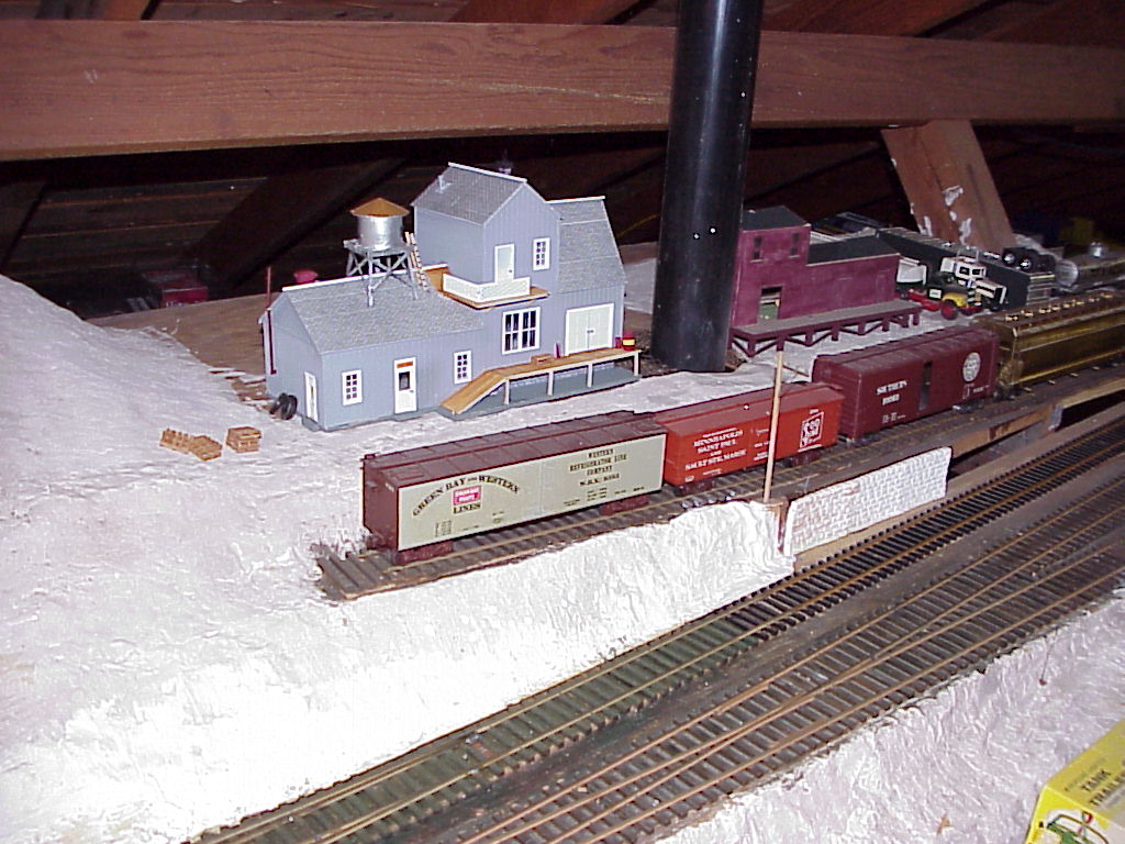
The 2 pictures immediately above are the east side of the south end of
the layout. The closest
turnout is a reversing track and the turnout in front of the 2
locomotives is part of the original
point to point turnaround.
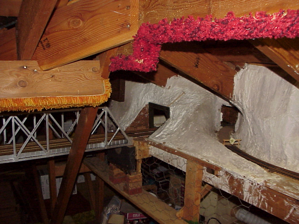
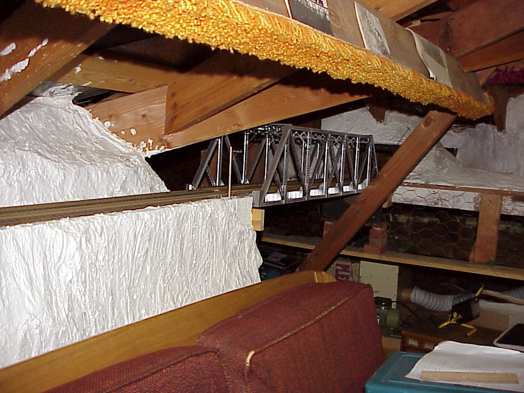
The northern portion of the layout is separated from the southern
portion with a valley spanned
on the west side with a dual track masonary arch bridge and the east
side with a wooden single
track trestle and the single track Overland truss bridge as described
in separate links on the home
page. Most of the layout has been covered with casting plaster or
hydrocal but only small parts
have the scenery completed.