Notes on Skew Control for LNB (for two Pansat
FTA Receivers)
11/9/14 - Trimble
A
big dish (LNB) skew
control was created to use a 3.3vdc voltage available on the Pansat
9200HD, Linkbox 8000Hd (and others) (0vdc for horizontal
polarity and 3.5vdc for vertical polarity).
For the set top boxes this voltage normally controls the voltage
to an LNBF (to yield 13 or 18v). This polarity control design
assumes that all satellites require the same polarity setting - except
for AMC 1 Ku band which is about 19 degrees off of the others. An
independent set of controls is included for AMC-1, manually
switched when needed.
Figure 1 and figure 2 shows the component side and bottom side of the
milled circuit board used.
Figure 1 - Skew control component
side Figure 2 - Skew control milled
circuit side
There
are 2 variable
resistors, one for horizontal and one for vertical, to allow tweaking
for the best signal angles, and once set
should not have to be adjusted again. An
independent pair of variable resistors are used for AMC-1 Ku band.
The
power supply
should have a voltage of 5vdc and sufficient amperage capability to
eliminate
any controller chatter due to slight variation of pulse length.
For
this design the
vertical adjustment is independent of the horizontal and the final
settings
need not yield exactly 90 degrees
between their directions. The output
pulse occurs at about 30ms periods.
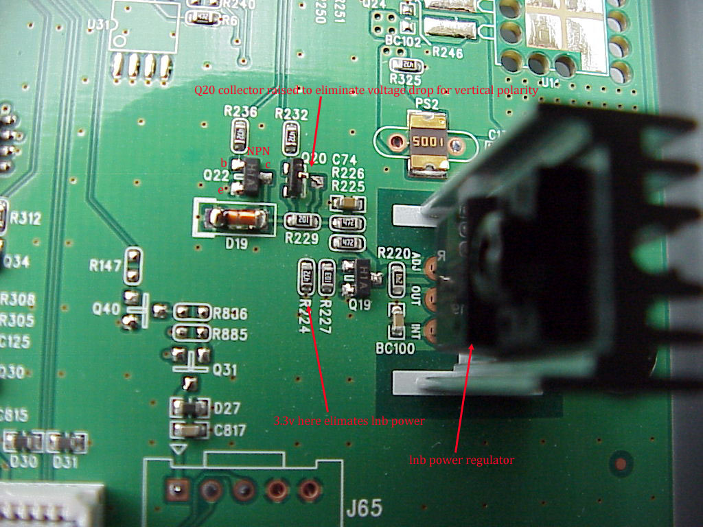
To obtain the 3.3vdc signal from the Pansat 9200HD see Figure 3 and
for the LInkbox 8000HD Local see Figure 4. On the Linkbox Local
a small pc board has to be lifted from its socker to access the portion
of the board shown. The wire connecting the 3.3vdc point on the
Pansat board should be isolated from the outside with a 100K resistor
as shown in Figure 5 so it can not be exposed to any significant load.
Figure
3 - 9200HD 3.3vdc
source
Figure 4 - Linkbox Local 3.3vdc source
Figure 5 - Isolation board
The lifting of the transistor noted in Figure 3 for the 9200HD may not
be necessary for many LNBs as they may operate on the 13vdc as well as
the 19vdc which is
the case for the LInkbox 14vdc/18vdc output.
Parts list:
Resistors
– (see
photo of top)
Variable resistors
(4) all 1k ohm
Timer chip 555
Comparator
chip LM311
Transistors
2N4401
and 2N3904E
Electrolytic 1000uf -
10v capacitor
Capacitor
- Tantulum
1uf (>5v)
Reed
Relay - single
pole, double throw ECG RLY F71C05C (5-6v, 0.25 amp coil)
Power supply - 5vdc 2500MA or better (most for DLINK Routers work -
ACY096 JTA0302B Power Supply on Ebay)